
A convincing particle-count result depends on more than camera resolution: the extraction method, filter, optical setup, reporting convention and validation controls all shape the answer. By the end, you will have a practical checklist for comparing optical systems, recognising unusable specifications and deciding when another cleanliness method is the better choice.
Key takeaways
- Define the extraction and reporting method before comparing analyzers.
- Request validated size, count, area and detection-limit data.
- Check whether software records images, particle dimensions and audit trails.
- Control extraction, filtration and blanks as one complete test system.
Start with the cleanliness method, not the instrument name
Decide what contamination decision you need before comparing instruments. For component cleanliness under ISO 16232:2018 or VDA 19.1, extract particles by flushing, rinsing, agitation or ultrasonication, collect the liquid, filter it, inspect the membrane, and report particles against the component or filter area. The extraction method is part of the test, not a laboratory detail.
For cleanliness particle analyzer optical IV selection, distinguish these methods:
| Method | Measures | Use it when |
|---|---|---|
| Component cleanliness | Particles recovered from a component and captured on a filter | You need particle size, images, morphology, fibres or evidence tied to one component |
| ISO 4406 | Particle concentration codes in hydraulic fluid | You need hydraulic-fluid cleanliness coding, not an ISO 16232 or VDA 19.1 component result |
| Online fluid monitoring | Suspended particles in a circulating fluid | You need continuous alarms in a pipe or process loop |
An online monitor is the wrong choice when you need particle images, morphology, fibre classification or proof that contamination came from one component. An optical filter analyzer is the wrong choice when the decision concerns continuous process alarms or total non-volatile-residue mass.
Ask the supplier to identify:
- The extraction procedure, filter preparation, particle detection, sizing, classification and reporting steps covered by the quoted method.
- Whether it reports particles per component, per filter or per unit area.
- The meaning of “DXEL filtrate optical IV,” including its filter medium, size convention and validation evidence.
That branded phrase is not a standard or complete test method.
Demand specifications that describe validated measurement limits
The useful lower limit is the smallest size the method has validated for reliable detection and sizing, not the membrane pore size. A 5 µm membrane does not prove reliable 5 µm detection: numerical aperture, camera pixel size, illumination, contrast, focus, calibration and the validated threshold determine the usable limit.
| Published figure | What it means | What to demand |
|---|---|---|
| Optical resolution limit | The smallest feature the optics and camera can distinguish | Evidence that particles at this size are detected and sized |
| Validated counting limit | The smallest size confirmed with test particles or production samples | Detection-efficiency and sizing results at the decision threshold |
| Software bin setting | A configurable reporting interval | Do not treat it as proof of optical performance |
For a particle analyzer for manufacturing, request the minimum validated particle size, maximum measurable size, size bins, count capacity, concentration limit and sizing accuracy. Ask whether each is an optical limit, a validated counting limit or only a software setting.
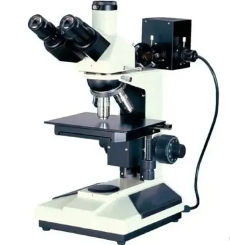
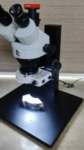
Check the optical principle, flow-cell dimensions, sample-volume range, pump type, controlled flow rate, flushing volume and rinse-cycle requirements. Confirm whether the system scans the complete usable filter, a defined area or selected fields, and whether it reports particles per filter, component or unit area.
Require end-to-end throughput covering filter loading, focusing, scanning, false-detection review, cleaning, remeasurement and report generation. Require traceable calibration for dimensional measurement and particle detection; ISO 11171 calibration for liquid particle counters does not validate an imaging system measuring particles on a filter.
Check what the software sees, counts and records
A release decision needs object-level evidence, not only a pass/fail total. Ask whether the cleanliness particle analyzer options report the following:
| Output | Evidence provided | Limitation |
|---|---|---|
| Particle count and size bins | Counts by defined diameter ranges | Totals hide shape and individual borderline objects |
| Equivalent circular diameter | Size of a circle with the same projected area | It is not true three-dimensional size |
| Longest dimension, length and width | Elongation and chip dimensions | Projection depends on particle orientation |
| Aspect ratio and fibre count | Separate evidence for wire-like contamination | Elongated chips can be misclassified as fibres |
| Particle images and object data | Reviewable proof behind a disputed count | A PDF-only summary is weak audit evidence |
| Mass | Residue quantity, if the system actually measures it | Optical imaging does not produce gravimetric mass |
Optical imaging measures a two-dimensional projection, not true three-dimensional size or mass. Do not compare its results directly with gravimetric residue or liquid-particle-counter data without a defined correlation.
Test transparent, translucent, reflective, dark, metallic, polymer, glass, machining-fine and fibrous reference particles. Detection efficiency changes with contrast and surface reflectivity.
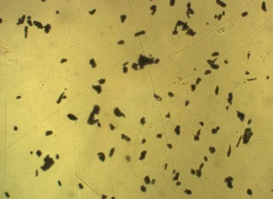
Check that the software separates touching and overlapping particles through adjustable segmentation, object review and a documented merged-object rule. Bubbles, droplets, membrane scratches, stains, folds and flow-cell debris can create false counts.
Preserve each result with sample identity, filter identity, operator, method version, calibration status, threshold settings, excluded regions, reviewed objects and original images. That record is what lets you defend a large-particle count during a customer dispute.
Validate extraction, filtration and blank controls as one system
Trust the optical result only after validating extraction, filtration and blank controls as one system. The analyzer cannot correct particles lost during rinsing or added during preparation.
1. Specify the contamination-test cabinet, component fixtures, rinsing nozzles, solvent or extraction-fluid compatibility, agitation method and ultrasonic capability with the analyzer. Match materials to the fluid; incompatible seals, plastics or coatings can shed particles or dissolve.
2. Define the recovery procedure for flushing, rinsing, agitation and ultrasonication separately. They do not recover contamination identically. Ultrasonication can detach weakly adhered particles, fracture agglomerates or introduce particles from the bath, fixture or vessel.
3. Confirm that filtration prevents particle loss, evaporation, recontamination and filter damage. Record filter material, pore size, wetting procedure, funnel or vessel design, forceps and drying conditions.
4. Run a blank membrane, extraction-fluid blank, equipment blank and handling control. These controls expose contamination from the membrane, forceps, funnels, vessels, air, cleaning tools and operators. A low instrument background does not prove a low method blank.
5. Require recovery data using representative reference particles or known production samples, not only a camera-resolution claim. Ask for repeatability and reproducibility at the actual limits, such as ≥15 µm, ≥50 µm and ≥100 µm.
When critical-particle counts are low, use replicate extractions or filters and define the acceptance rule before testing. State whether a blank count is subtracted, reported separately or causes a failed run.
Compare the complete workflow before choosing an optical IV system
Choose the method that answers your contamination decision, not the system with the largest magnification or fastest image rate. Compare the complete chain: component fixture, extraction cabinet, rinse, filter, analyzer, review software, blanks, calibration, cleaning and report.
| Option | Strongest evidence | Main limitation |
|---|---|---|
| Optical imaging | Morphology, location, size distribution and fibres | Does not directly measure residue mass |
| Gravimetric analysis | Total non-volatile residue mass | Does not identify particle shape or location |
| Online liquid monitoring | Suspended-fluid alarms and continuous trends | Does not prove contamination came from one component |
A manufacturing laboratory may need two methods because no single instrument reliably measures mass, morphology and every particle type. Compare cleanliness particle analyzer options against the release decision and reporting route under ISO 16232:2018 or VDA 19.1, not against a headline specification.
For the DXel-Filtrate Optical IV, ask the supplier to document:
- Filter medium, extraction method, optical configuration, size convention, measurable range and concentration limit.
- Flow-cell dimensions, pump details, validation samples and calibration for both particle detection and dimensional measurement; ISO 11171 calibration for a liquid counter does not validate filter imaging.
- Blank procedure, cleaning cycle, image review, repeatability at ≥15 µm, ≥50 µm and ≥100 µm, and the ISO 16232/VDA 19.1 report path.
Confirm when CTC-S10 rinsing or agitation is required for valid recovery and how it connects to the analyzer. Conation Technologies Pvt. Ltd. is worth evaluating here if it supplies both units, because method integration matters more than an isolated camera specification.
Related products
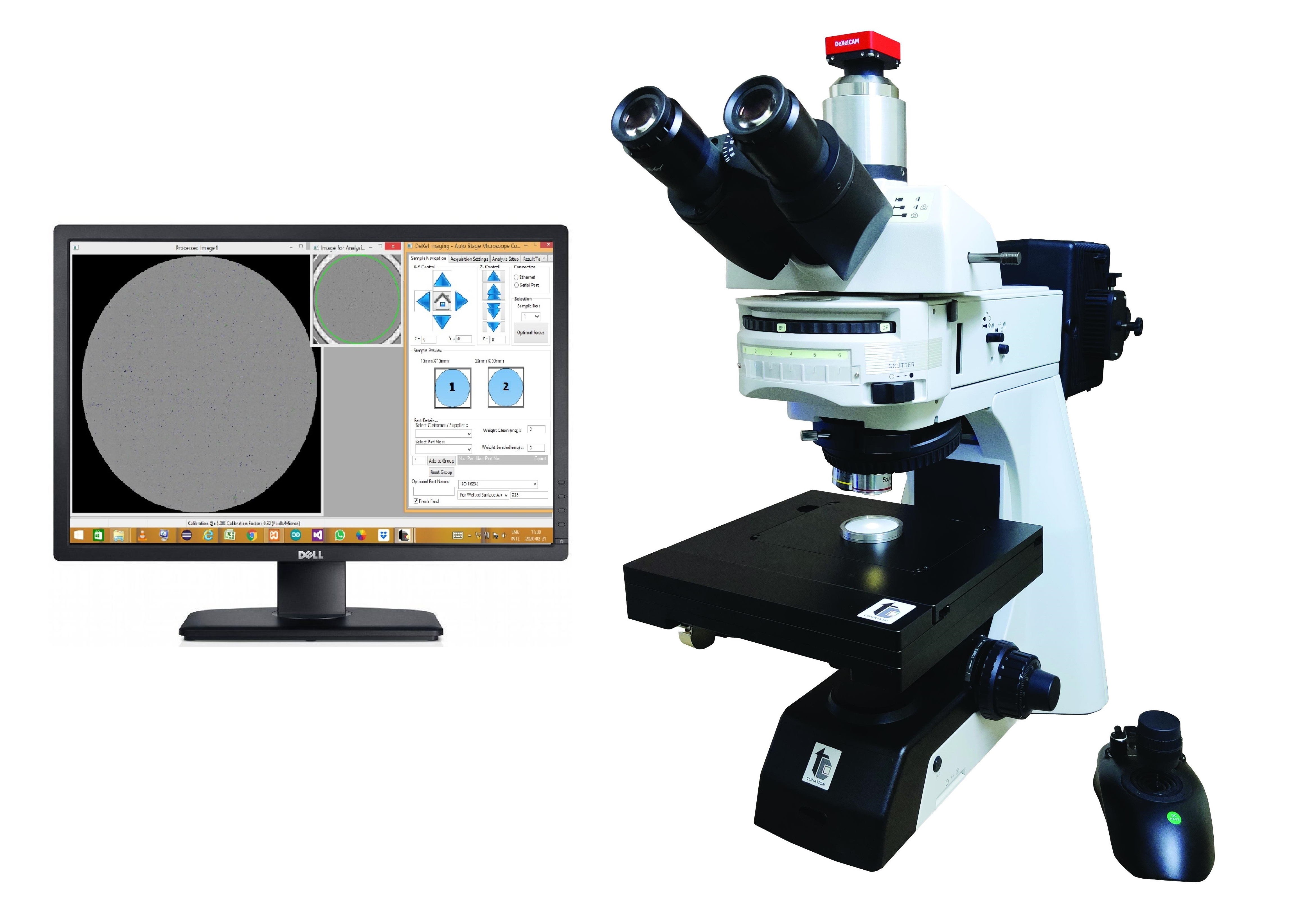 | Cleanliness Particle Analyzers DXel-Filtrate Optical IV; Automatic Particle Analysis System Critical components going into fluid or air circuitry, engine components and some trasmission assemblies are need to free from particle contamination... View product → |
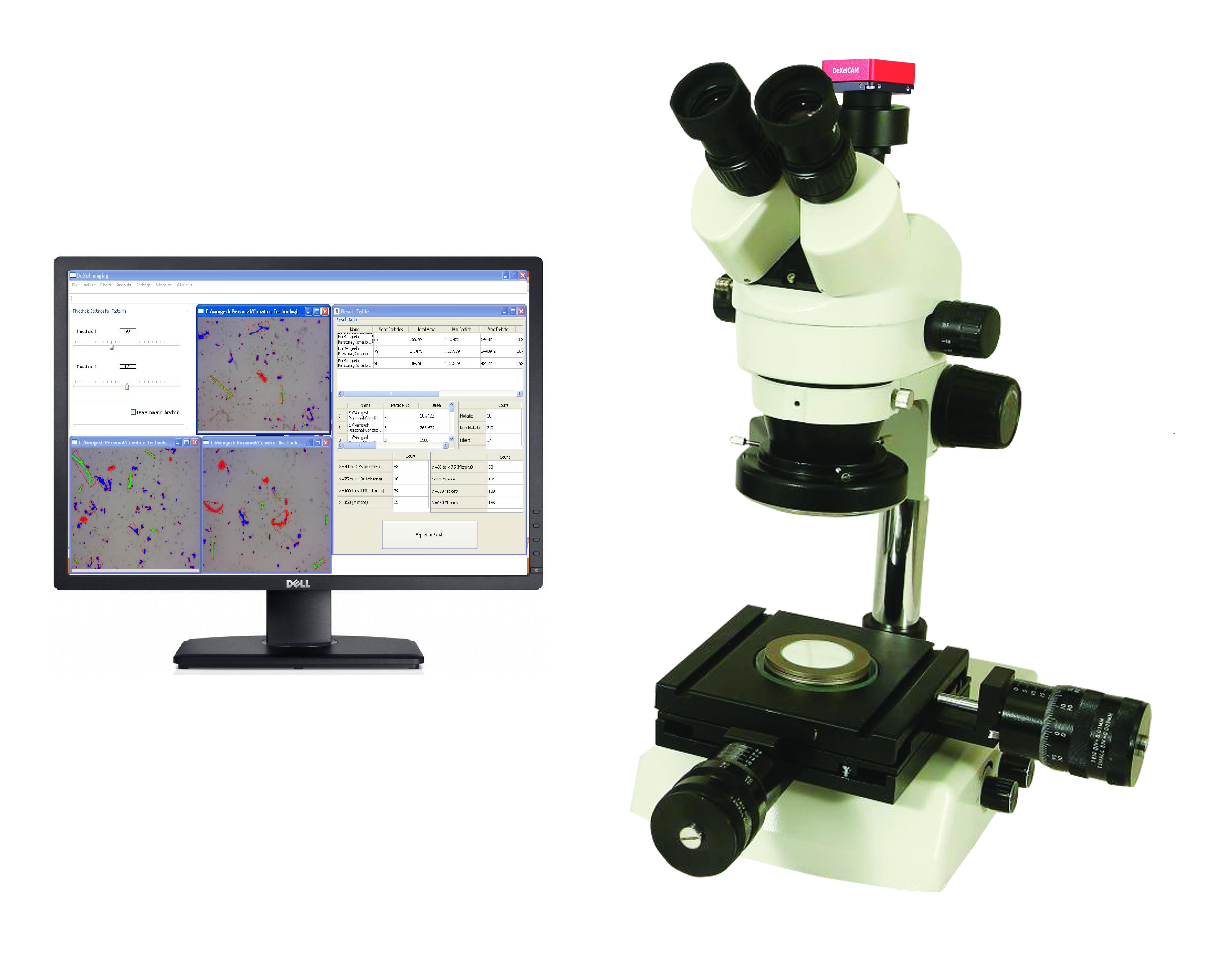 | Cleanliness Particle Analyzers Filtrate I - Semi-Automatic Particle Analyzer Critical components going into fluid or air circuitry, engine components and some trasmission assemblies are need to free from particle contamination... View product → |
Frequently asked questions
Why should you choose the cleanliness method before the instrument?
ISO 16232:2018 and VDA 19.1 cleanliness tests depend on extraction, filtration, membrane inspection and reporting rules. The analyzer must fit that complete method.
Which specifications matter when comparing optical IV particle analyzers?
Request validated particle-size ranges, detection limits, counting capacity, measurement uncertainty, inspected area and performance with your actual filter type.
What should cleanliness-analysis software record?
Check that it records particle counts, dimensions, images or classification data, filter area, sample identification, operator actions and an auditable test report.
Why validate extraction, filtration and blank controls together?
Poor extraction leaves contamination on the component, while dirty fluids or filters raise false counts. Run blank controls through the same fluids, equipment and filtration process.
How should you compare the complete workflow before selecting an optical IV system?
Compare sample preparation, filtration, transfer, microscope or analyzer setup, review time, reporting, cleaning, calibration and operator training—not only instrument specifications.
Related products
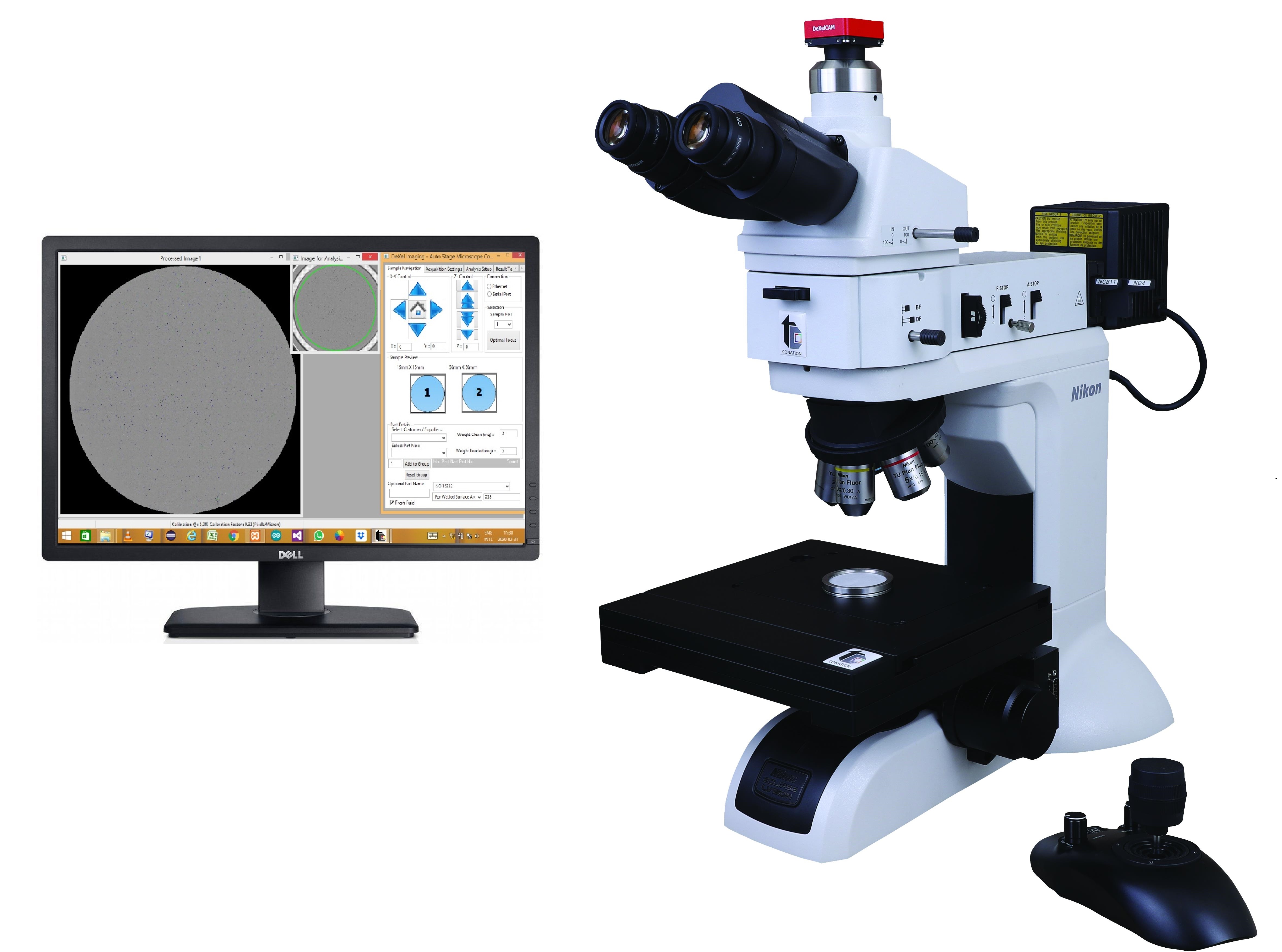 | Cleanliness Particle Analyzers DeXel-Filtrate Optical NLV; Automatic Particle Analysis System Critical components going into fluid or air circuitry, engine components and some trasmission assemblies are need to free from particle contamination... View product → |
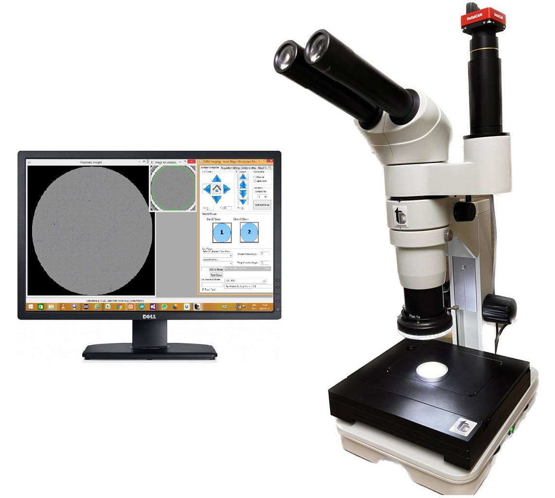 | Cleanliness Particle Analyzers Critical components going into fluid or air circuitry, engine components and some trasmission assemblies are need to free from particle contamination... View product → |